AVR microcontroller based PWM fan controllers
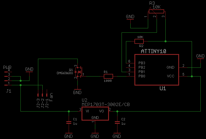
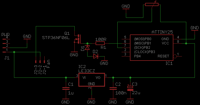
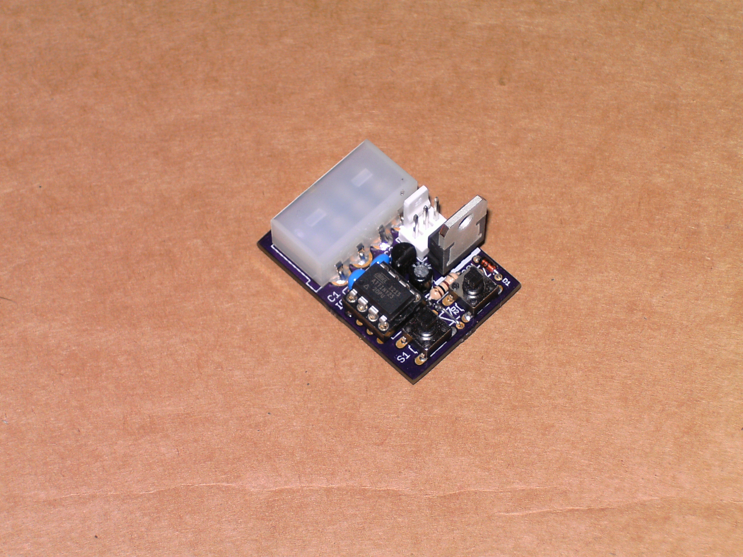
So this is a bit of a continuation on my 555 timer based PWM controllers, but now using microcontrollers and MOSFETs instead of 555 ICs and transistors. I made 2 versions, one with switches for speeding up and down and the other with a potentiometer like the previous controllers. I used ATtiny25 controllers running at 31.25KHz (8MHz internal RC / 256 prescaler) with a 3.3V supply, the MOSFETs I used are STP36NF06L with 0.045Rds and 2.5Vgs max, perfect for 3.3V, the MOSFETs only generate ~180mW of heat at 2A ((0.045Rds * (2A ^ 2)) = 0.18W) so no heatsink needed, you can barely feel them getting warm.
In the schematics change R1 from 100R to 150R if you use a 5V supply to keep the current under 40mA (remember, MOSFET gates need to be charged and discharged and doing this without a resistor is going to send large currents though the uC), the zener diodes D1 and D2 are for ESD protection and need to be rated somewhere between a few volts above the uC supply voltage and below the max gate voltage for the MOSFET, usually 20V, I used 12V zeners, they can be removed if you think you don’t need them, some MOSFETs have them built in. D2 is not actually needed even if you do want ESD protection since we aren’t using any negative voltages at the MOSFET gate.
The STP36NF06L MOSFETs can easily switch ~8A as they are in the circuits, but some heatsinking will be needed and a 5V supply is recommended, wiring up 2 MOSFETs in parallel will reduce total heat generated (make sure they’re both on the same heatsink), but don’t forget appropriate gate resistors like a 56R which then splits to two 150R which go to the gates, max gate current will then be ~39mA. The potentiometer can be almost any value, but too high will cause the microcontroller ADC to return incorrect readings and too low will cause excessive current drain, I used 22K since it was on special offer for £0.17 instead of £0.43, but anywhere between 4.7K and 22K will be fine.
Update - 10 July 2013
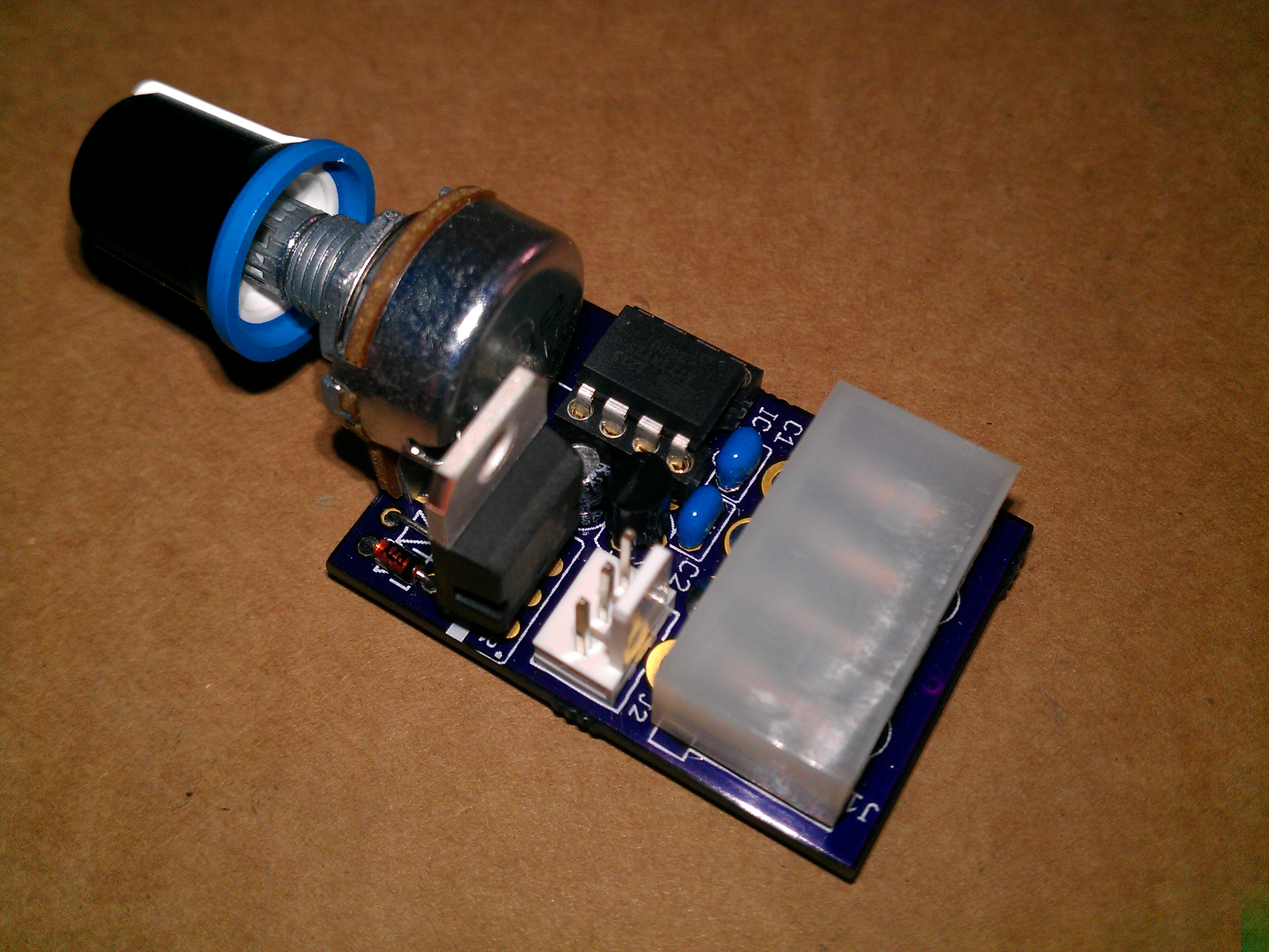
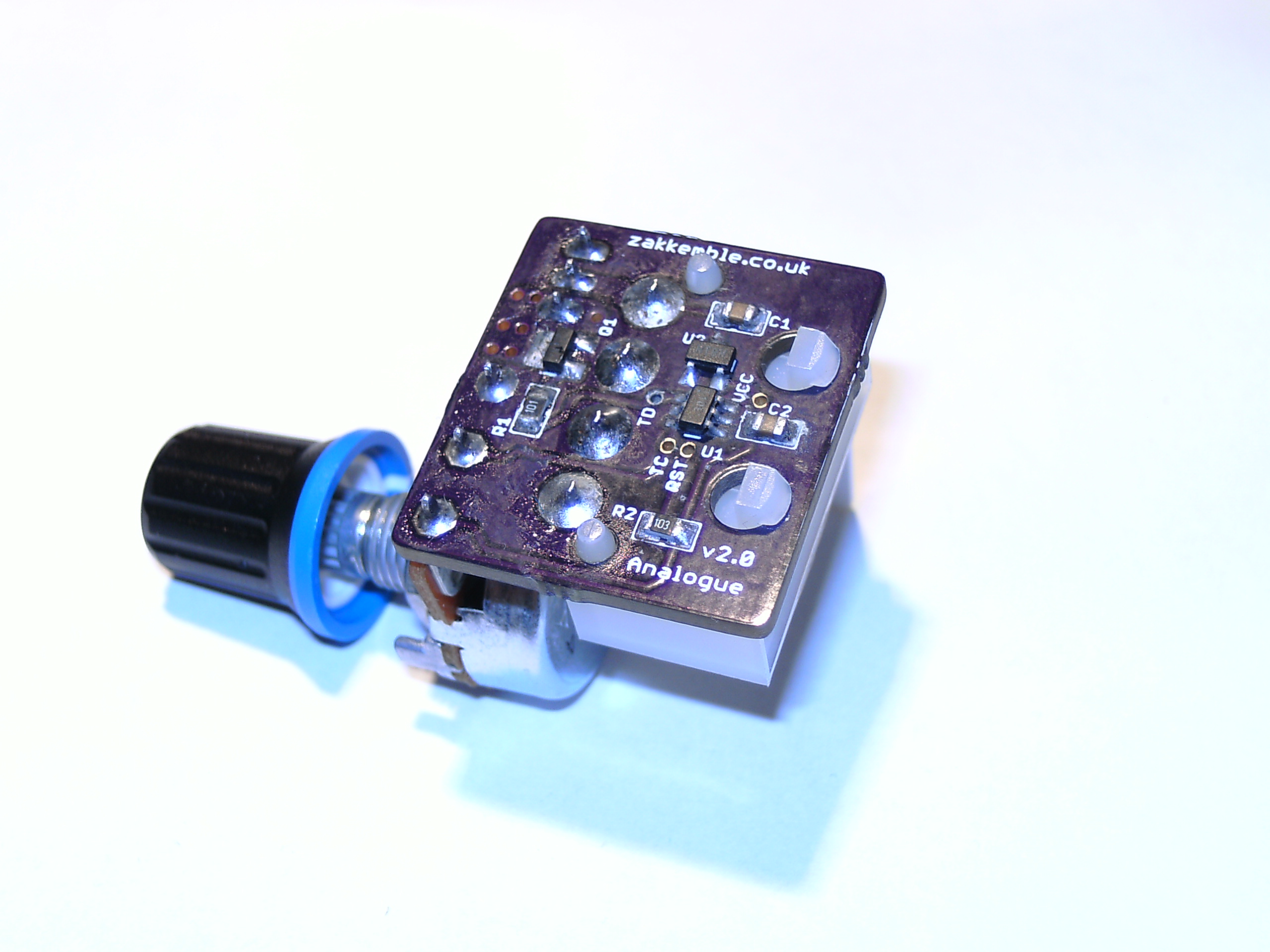
New SMD edition using an ATtiny5/10 microcontroller and DMG6968U MOSFET (has built-in zener diodes for ESD protection), no problem switching 2-3A.
Downloads
LATEST

|
fanController_20130710.zip (203 KB)
fanController_20130710.zip MD5: 4C794E8C2CAB0CE65C79DDAF65E04CC2 |
|
OLD
|
fanController_20120803.zip (179.94 KB)
fanController_20120803.zip MD5: A862B6D96A8FCF6A0CE9C9DF90B749EB |
|
OLD
|
fanController_20120802.zip (179.69 KB)
fanController_20120802.zip MD5: 680379F31E75CB81A86E62E2B5727786 |
|
OLD
|
fanController_20120729.zip (179.02 KB)
fanController_20120729.zip MD5: C0BDAD5FBF993473E65380AFB7F87193 |
|
|

|
|
|
|

Comments
Skip to comment form