Modifying RAM SPD Data
Recently I brought some low-power Mini-ITX motherboards; a Gigabyte GA-N3050N-D3H and a Biostar N3050NH. These boards take SO-DIMM DDR3 RAM, the sort found in laptops.
The boards are both pretty much the same, however the Gigabyte board lacks quite a few BIOS features and settings that the Biostar board has. One of those missing features was being able to set the RAM frequency. I wanted to run the RAM at its lowest frequency of 800MHz, but the Gigabyte board would run it at the its normal frequency of 1600MHz. Running at 800MHz reduced idle power consumption by about 0.12W on the Biostar board, a ~2% reduction… yeah ok, it’s a teeny tiny amount, but it was just a matter of flicking a switch.
To remedy this it looked like I was going to have to modify the RAMs Serial Presence Detect (SPD) data. The SPD data is a set of configuration parameters stored in a small EEPROM chip that the BIOS reads at startup. The SPD EEPROM communicates using SMBus, which is mostly compatible with I2C available on an Arduino.
Modifying the SPD isn’t a new thing, there are numerous programs around the web that do SPD stuff, but they seem to be very hit and miss with software and hardware compatibility.
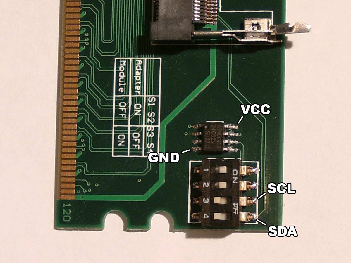
To prevent messing up the RAM modules when attaching wires to the SPD EEPROM I brought a DDR3 DIMM to SO-DIMM converter. These converters do work, just make sure the DIL switch is set to use the RAM module SPD and not the adapter SPD. Unfortunately, I have no idea what configuration the adapter SPD originally had since I accidentally wrote over it. :(
If you’re trying to mod a full size DIMM RAM SPD then you’re probably going to have to solder directly onto the module.
|
|
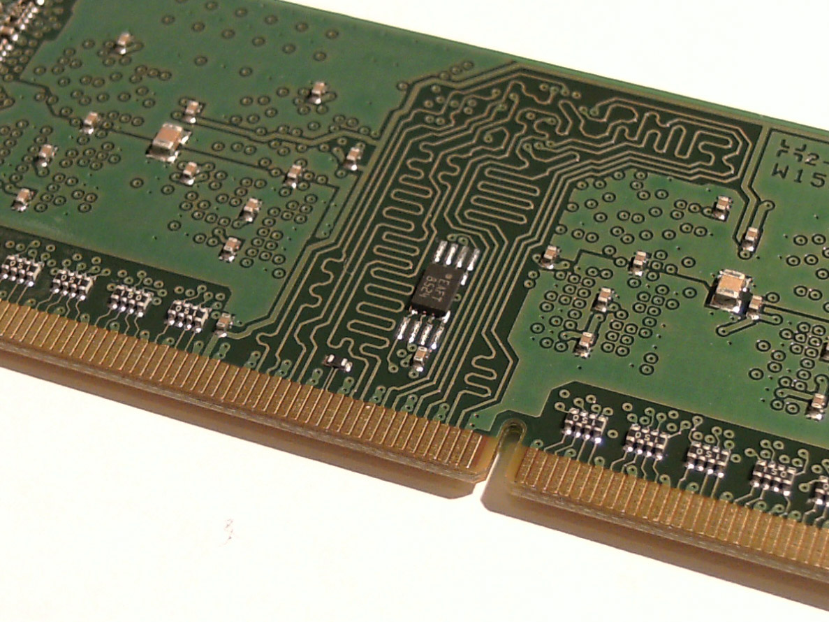
The SPD chip on this module (Kingston KVR16LS11S6/2) is an Atmel AT34C02, which can run on 1.8V – 5.5V so no need to worry about damaging the chip when powering it with an Arduino.
The EEPROM size is 256 bytes. Some parts of the SPD can be used for storing custom data, like bytes 150 – 175 which is “Manufacturer specific data” and if you’re not bothered about XMP then bytes 176-254 can be used. Maybe a super-secret password could be hidden there, who would think of looking for that kind of thing on a RAM module?
These EEPROM chips often have a write protection feature that prevents modification to its contents. I had expected the RAM module manufacturer to have this enabled, but to my surprise it was disabled! That made things a lot easier. More about write protection at the end.
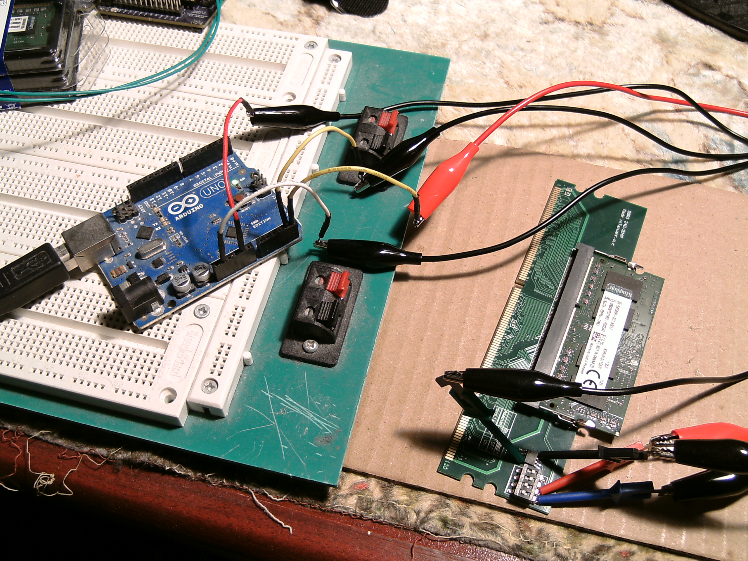
An Arduino Uno was used to read the SPD, modify the necessary bytes and write the changes back to it.
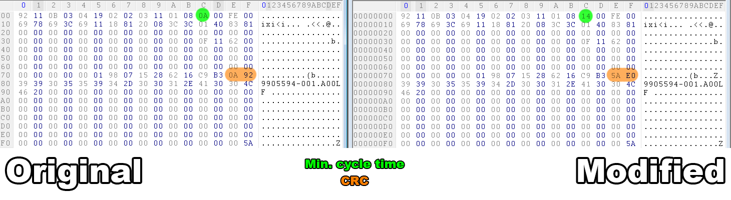
Only a few bytes needed to be modified to configure the RAM to run at 800MHz; byte 12 is the main one which contains the minimum cycle time in multiples of the MTB (bytes 10 and 11), and bytes 126 and 127 which contains the CRC.
Changing byte 12 from 0x0A to 0x14 sets the maximum clock rate to 800MHz. The CRC then needed to be recalculated using the CRC-CCITT XModem algorithm.
Output from $ dmidecode --type=17:
$dmidecode --type=17
Memory Device
        Array Handle: 0x0028
        Error Information Handle: Not Provided
        Total Width: 64 bits
        Data Width: 64 bits
        Size: 2048 MB
        Form Factor: DIMM
        Set: None
        Locator: A1_DIMM0
        Bank Locator: A1_BANK0
        Type: DDR3
        Type Detail: Unknown
        Speed: 800 MHz			<<<==========
        Manufacturer: Kingston
        Serial Number: 6216C9B3
        Asset Tag: A1_AssetTagNum0
        Part Number: 9905594-001.A00LF
        Rank: 1
        Configured Clock Speed: 800 MHz		<<<==========
        Minimum voltage:  1.350 V
        Maximum voltage:  1.500 V
        Configured voltage:  1.350 V
It works! 😀
The Arduino code and various other things are available on the GitHub repo.
Tested modules:
Kingston KVR16LS11S6/2 (1600MHz) (two modules, one containing Kingston RAM chips and the other containing Nanya chips)
Kingston KVR13LS9S6/2 (1333MHz)
Something I noticed was that between the two KVR16LS11S6 1600MHz modules there was a small difference in the SPD configuration; the module with Kingston chips supported PASR (Partial Array Self Refresh) while the Nanya module only supported ASR. The difference being that PASR allows just parts of the RAM to be refreshed instead of all of the whole thing, resulting in lower power consumption when in standby mode [more info].
I also noticed that the KVR13LS9S6 1333MHz module used the same Nanya RAM chips as the KVR16LS11S6 1600MHz module, setting the max frequency to 1600MHz seemed to work without any issues.

Write protection
There are usually 3 levels of write protection. Keep in mind that these might differ slightly between EEPROM chips, be sure to check the datasheet!
Hardware write protection
When the WP pin is connected to VCC the entire contents of the EEPROM is write protected. This one is the easiest to circumvent; simply disconnecting the WP pin will disable write protection.
Reversible software write protection
This one is a little bit trickier to circumvent. Not all EEPROMs support this mode, attempting to use this method may damage the chip! A2 must be disconnected or connected to GND, A1 to VCC and A0 connected to a 7V – 10V supply, like a 9V battery. Then send the 0x66 command to clear the write protection setting.
Permanent software write protection
If the EEPROM is permanently write protected, then you’re out of luck. The chip will need to be replaced with a new one.
I also found that a Gigabyte GA-M68M-S2P motherboard with Hypertec HYUK26412882GBOE DDR2 RAM can read and write the SPD EEPROM with Linux Debian. I wrote a few bash scripts to dump and write the SPD which are available in the GitHub repo.

Comments
Skip to comment form