IoT and a Door Entry System
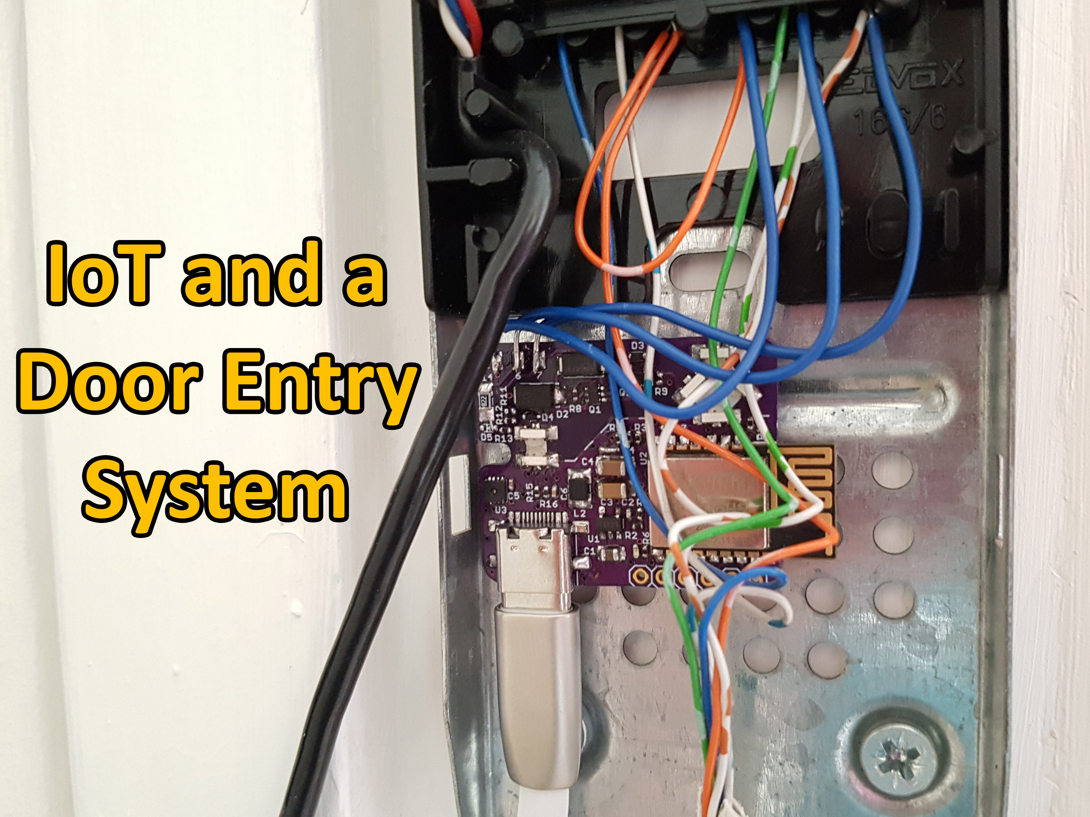
I recently moved into a two-floor apartment with a door intercom system on the bottom floor for the building lobby area. Since I’m normally upstairs I wanted to have some way of being able to unlock the door without having to rush down to the intercom when the postman rings. Being able to unlock the door remotely and knowing when someone rings when I’m out would be pretty neat too!
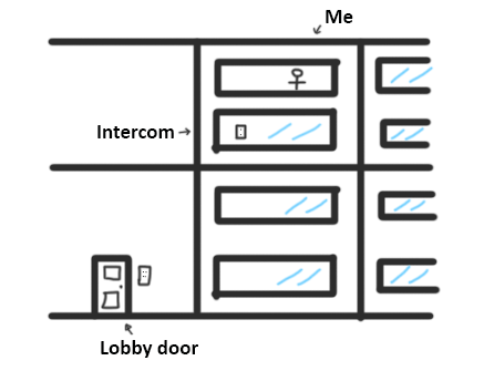
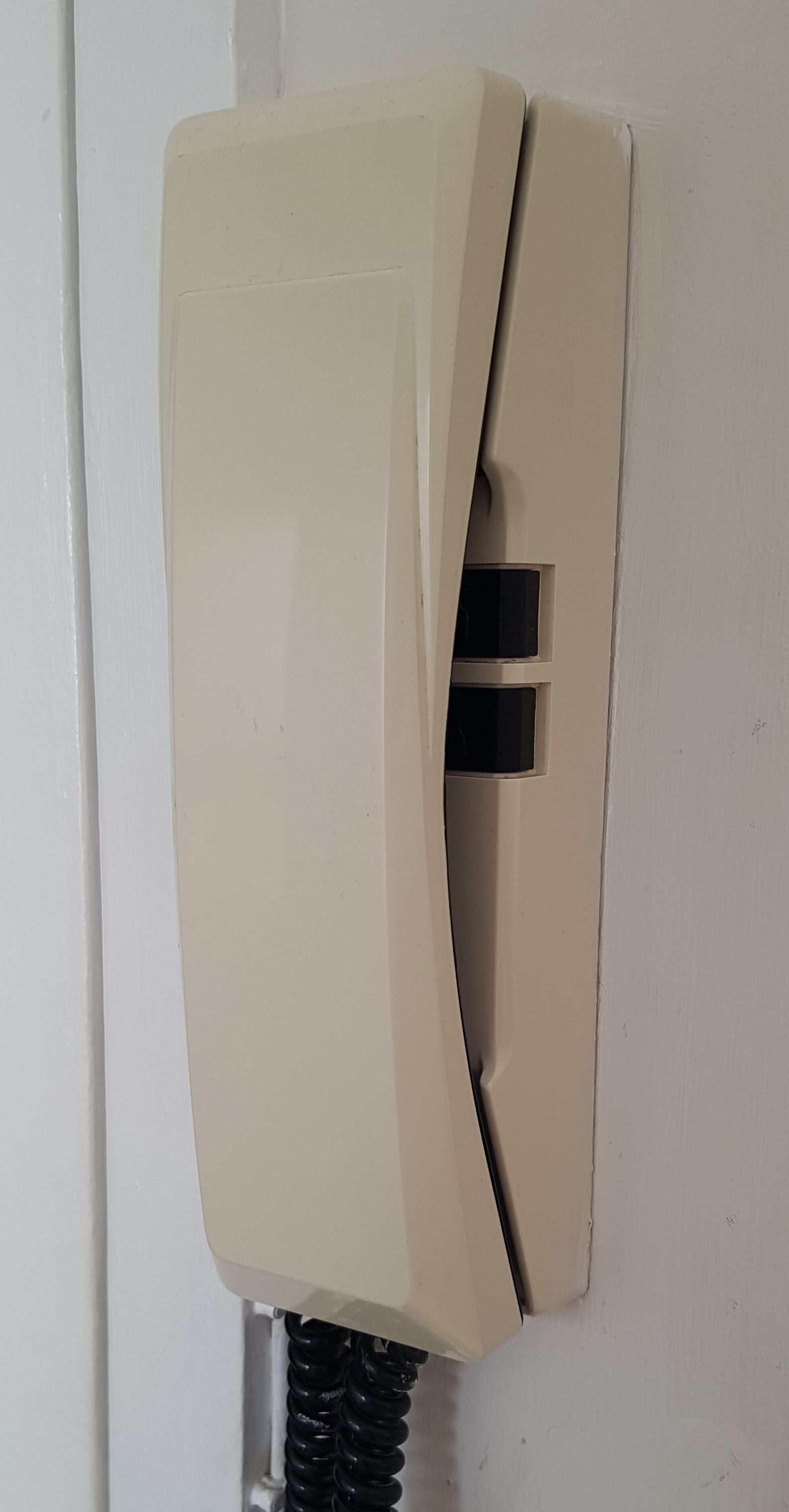
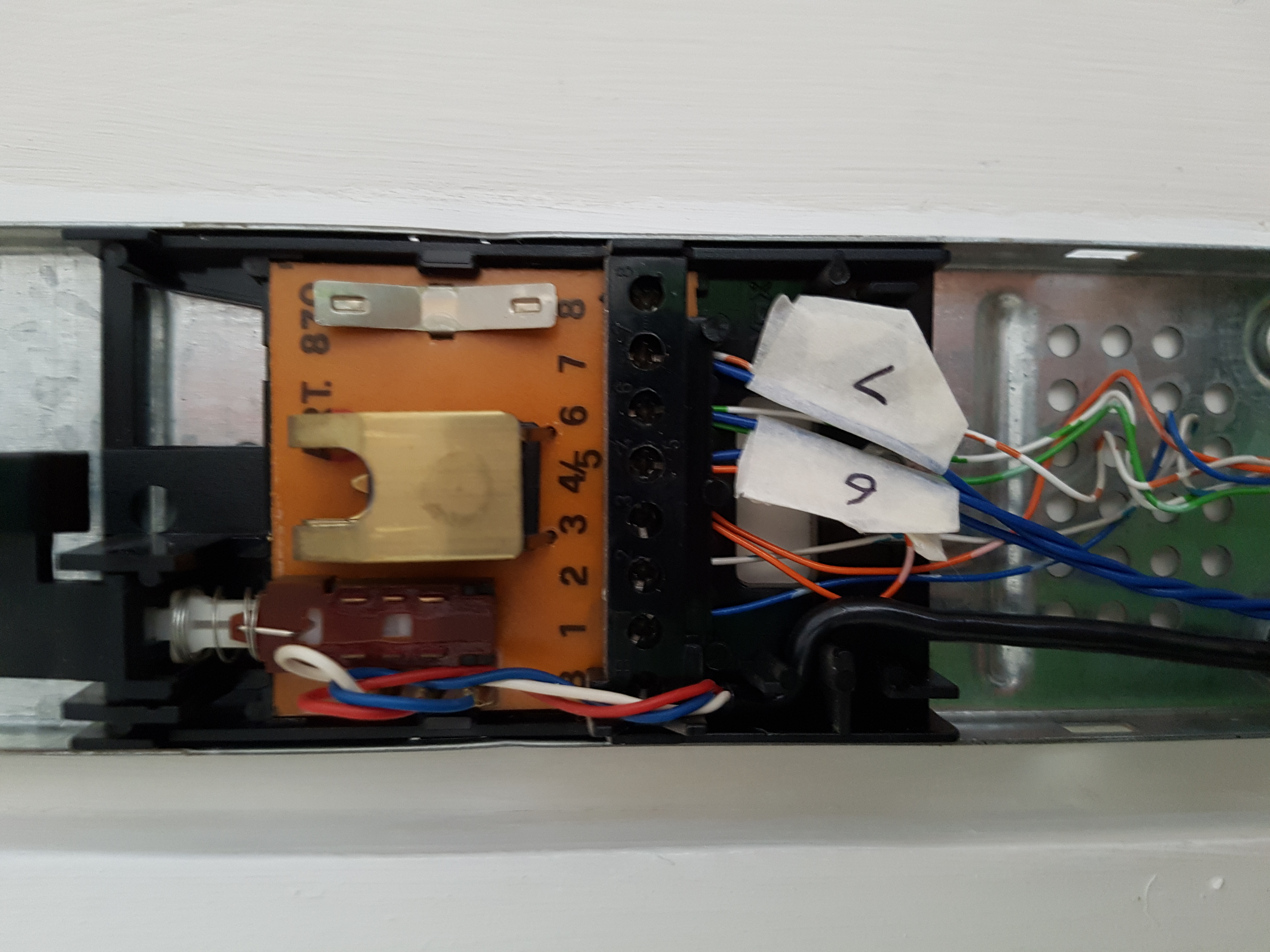
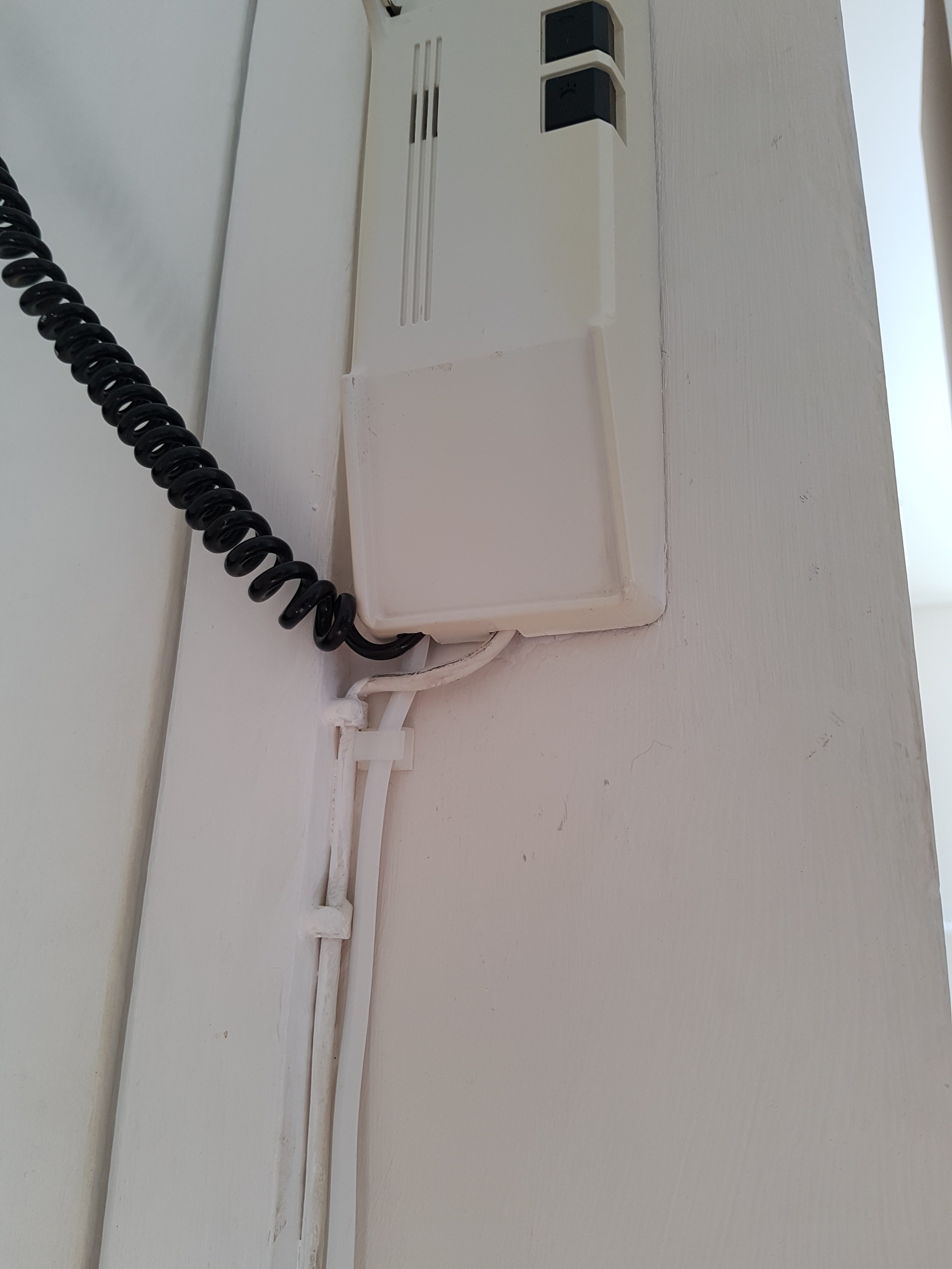
The apartment intercom system has the usual basic setup; it has a buzzer, a button for unlocking the lobby door and a handset to talk to whoever is wanting to come in, although the microphone doesn’t work in my intercom. It’s supplied with 14V AC and it’s also rather electrically noisy; there’s no inductive voltage spike suppression and small arcs are often seen when releasing the button that controls the solenoid for unlocking the lobby door, something I’ll need to be careful of when connecting a controller. It also causes the error counter on my broadband modem to go up by 1 every time it’s pressed!
|
|
The System
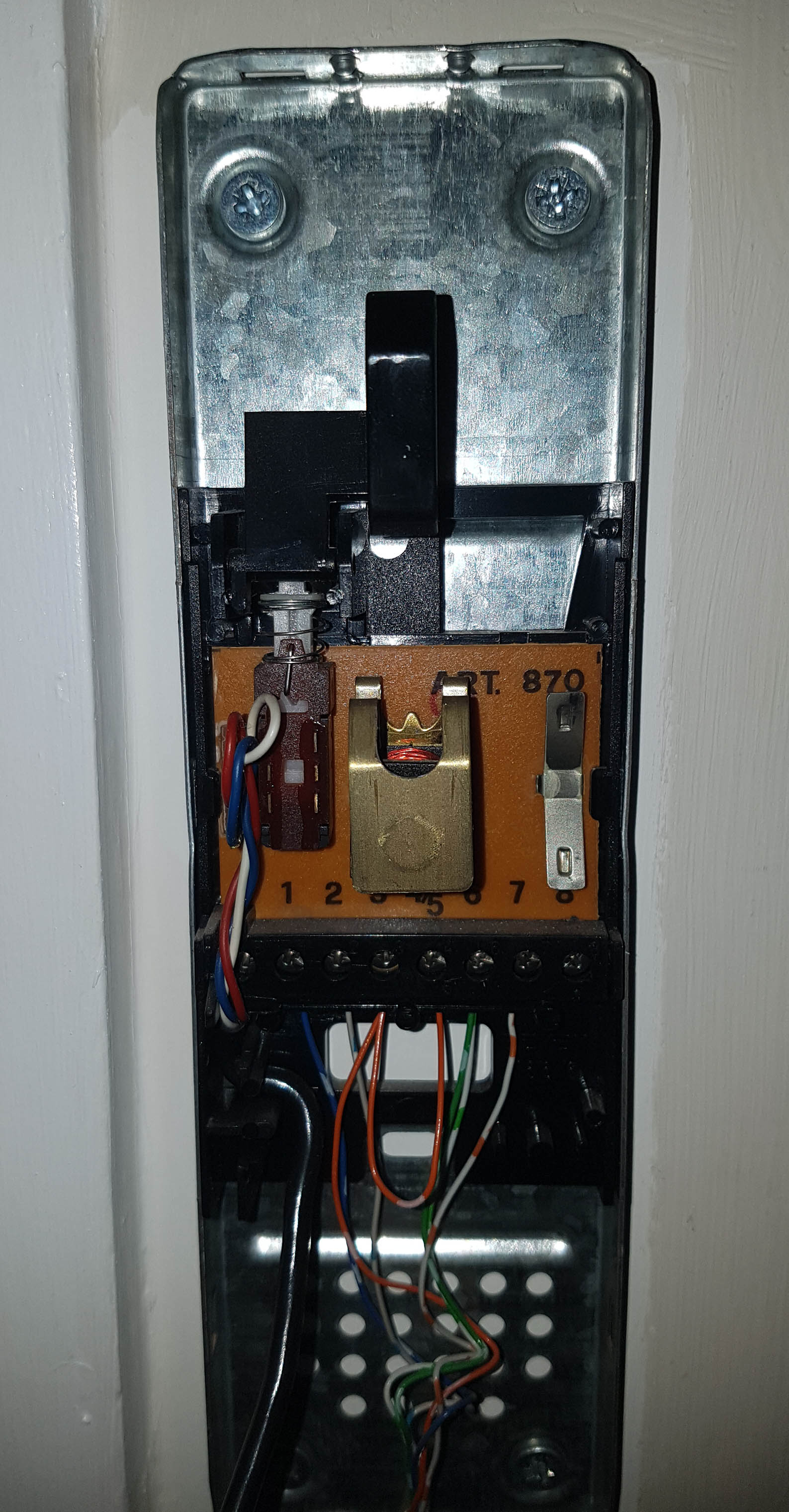
The first thing to do was to find some schematics of the system and try to figure out which wires do what. After searching for the manufacturer “Elvox” and “art 870” which were printed on the PCB inside I found plenty of information.
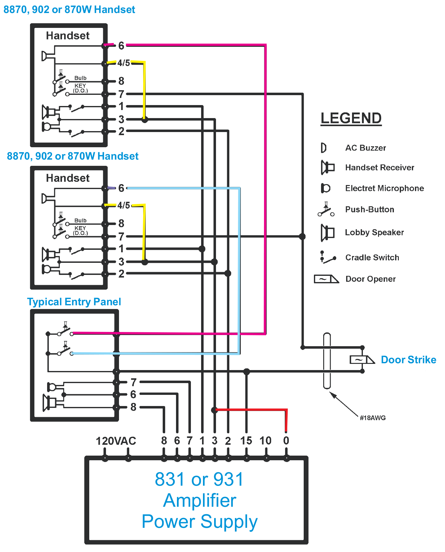
So, it looks like I need to sense the ring in (connection 6) for an AC signal and make a connection across the door open switch to open the door lock (connection 7 to 4/5).
Prototype
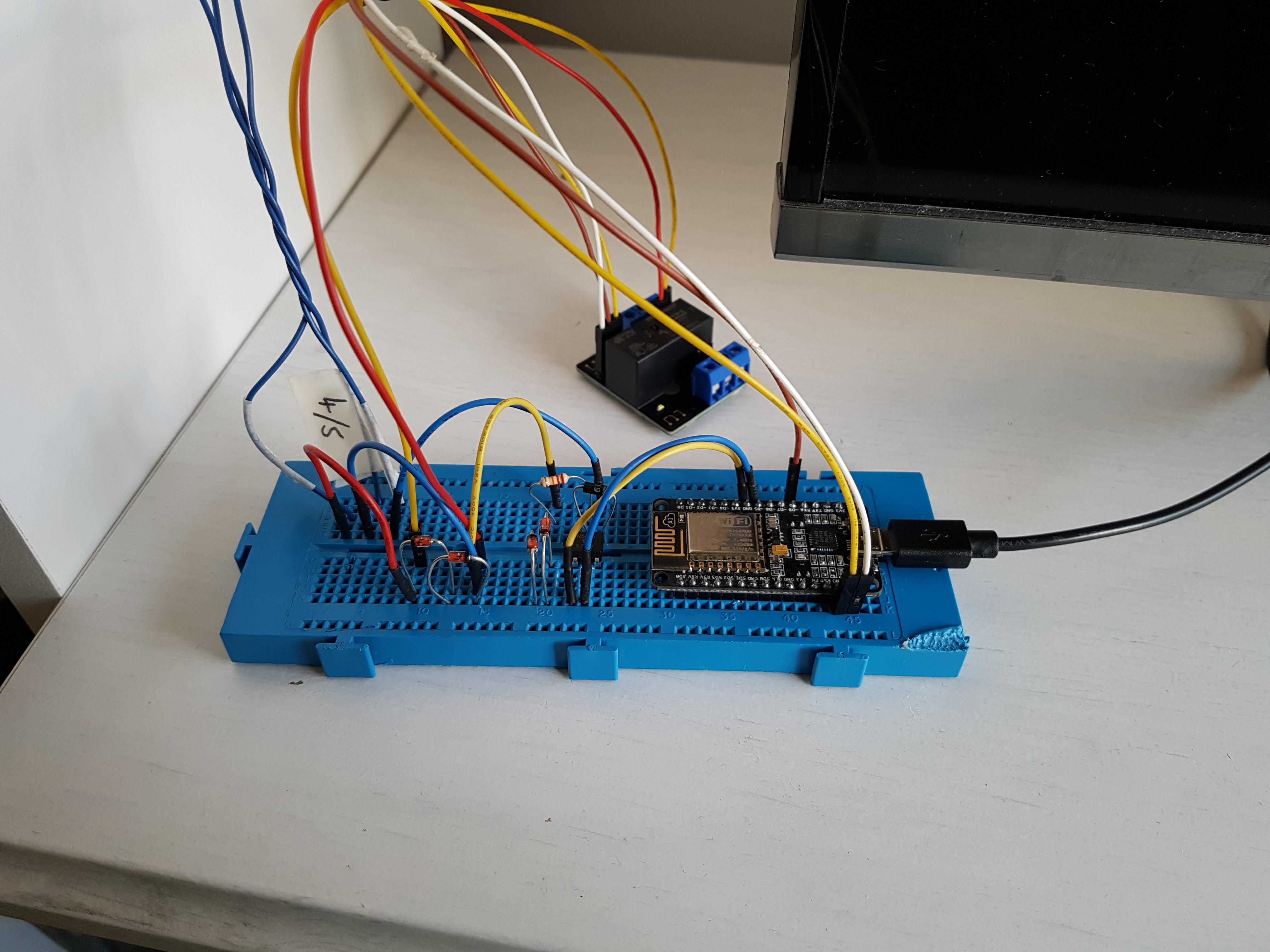
A prototype was built using a NodeESP board, an opto-coupler hooked to the ring input and a relay to the lock solenoid. It worked, the ESP could detect buzzes through the opto-coupler and the relay activated the door lock solenoid. So let’s get the real thing designed so that it fits neatly inside the intercom housing!
|
|
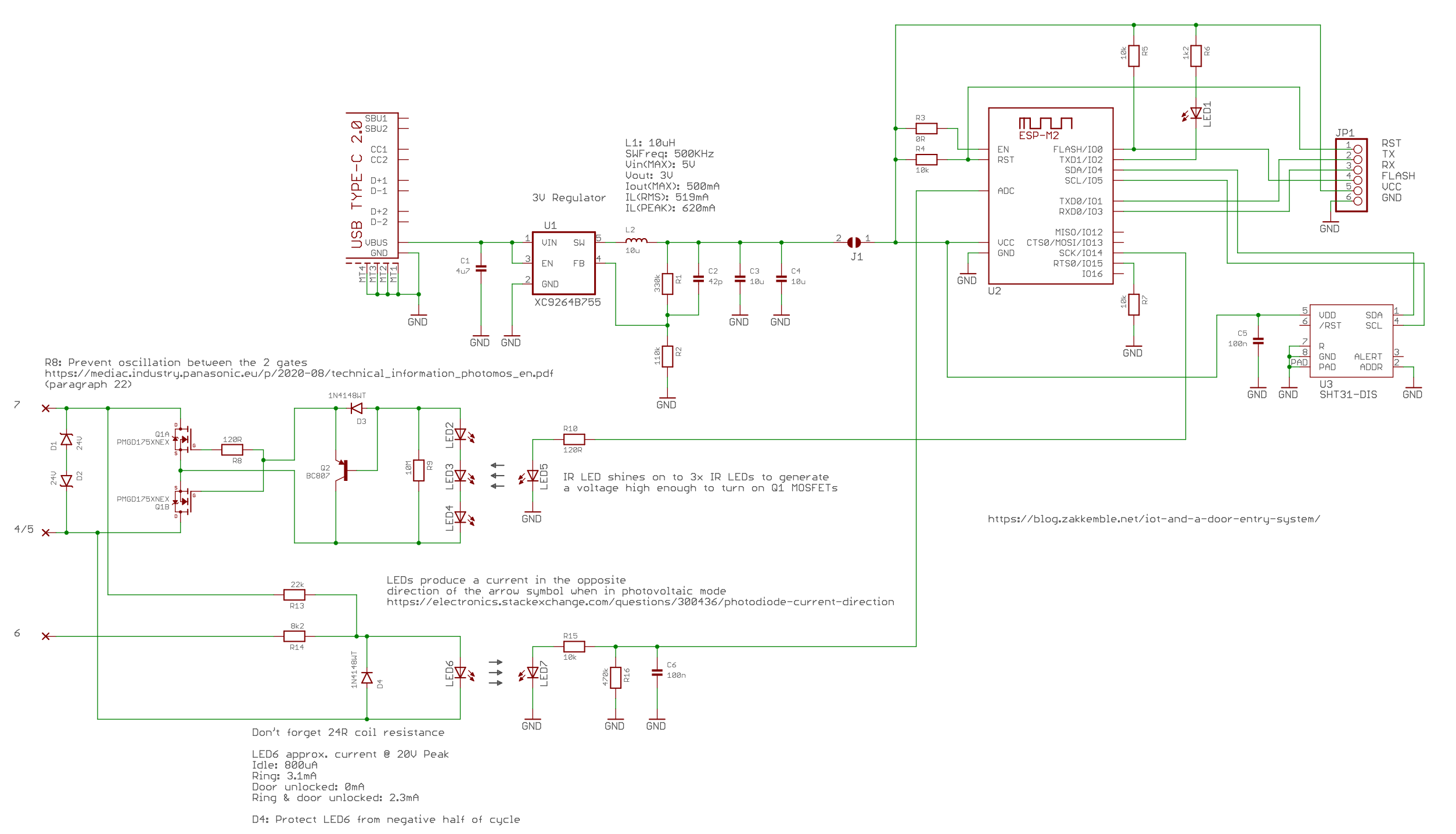
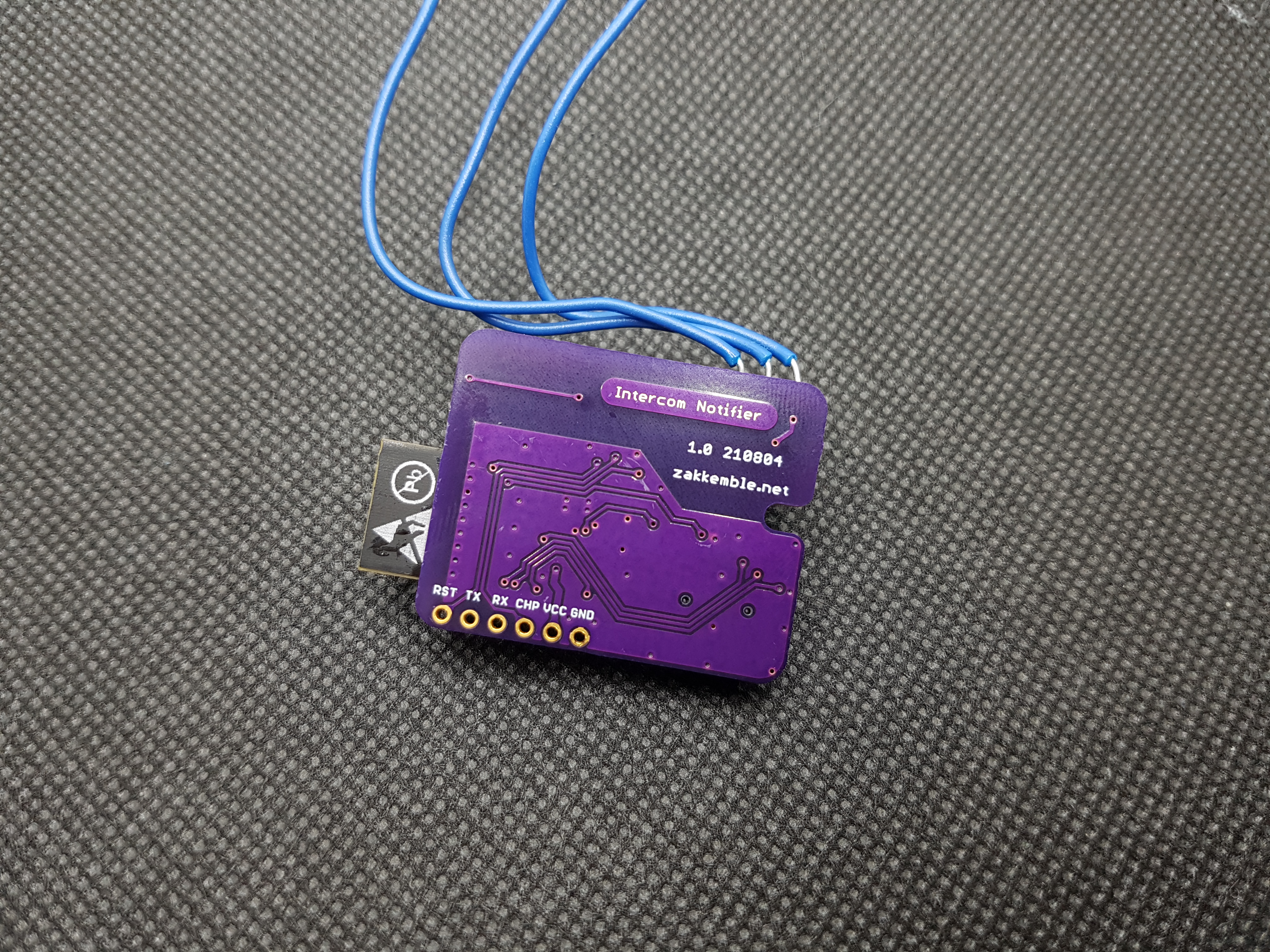
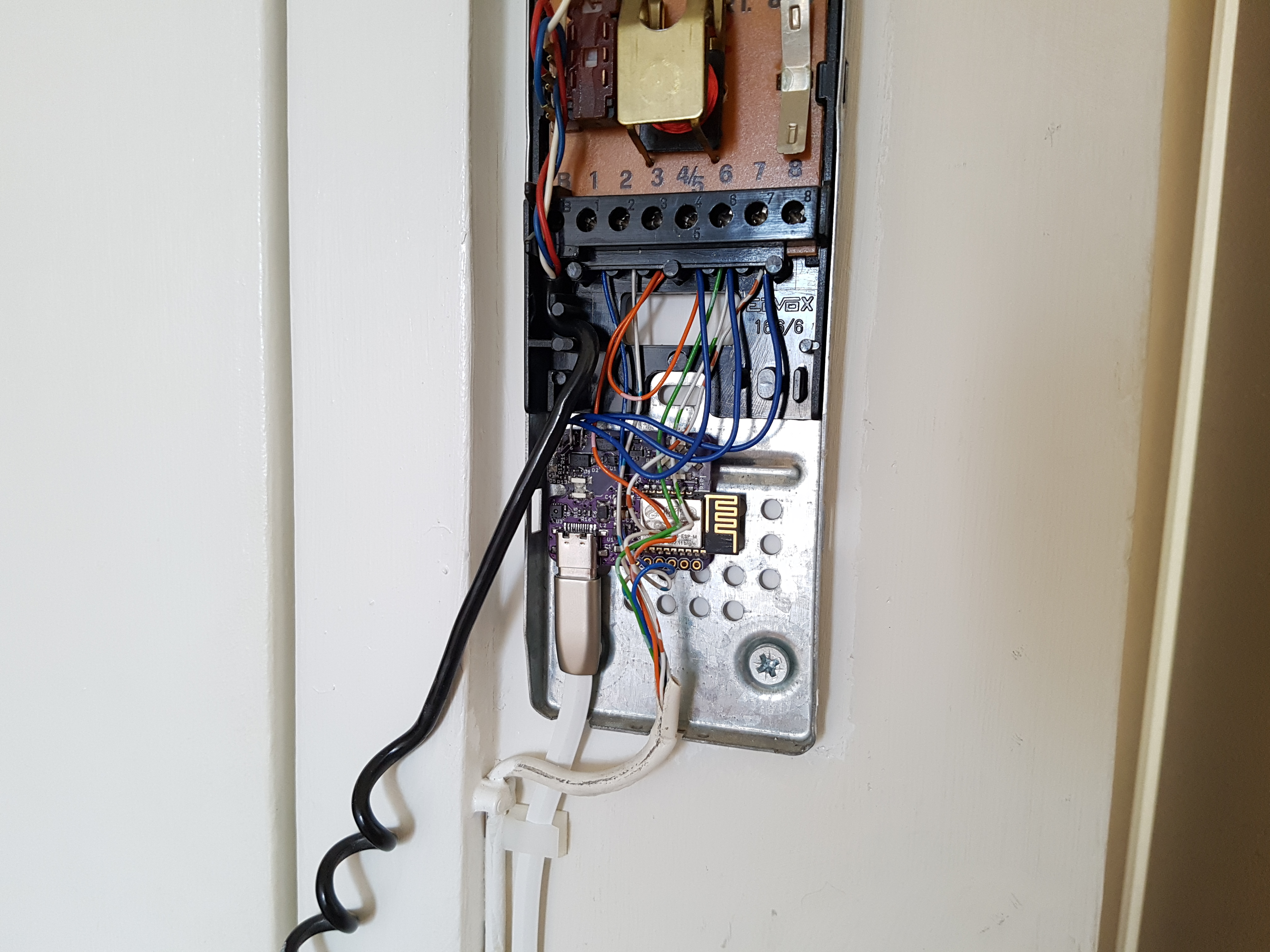
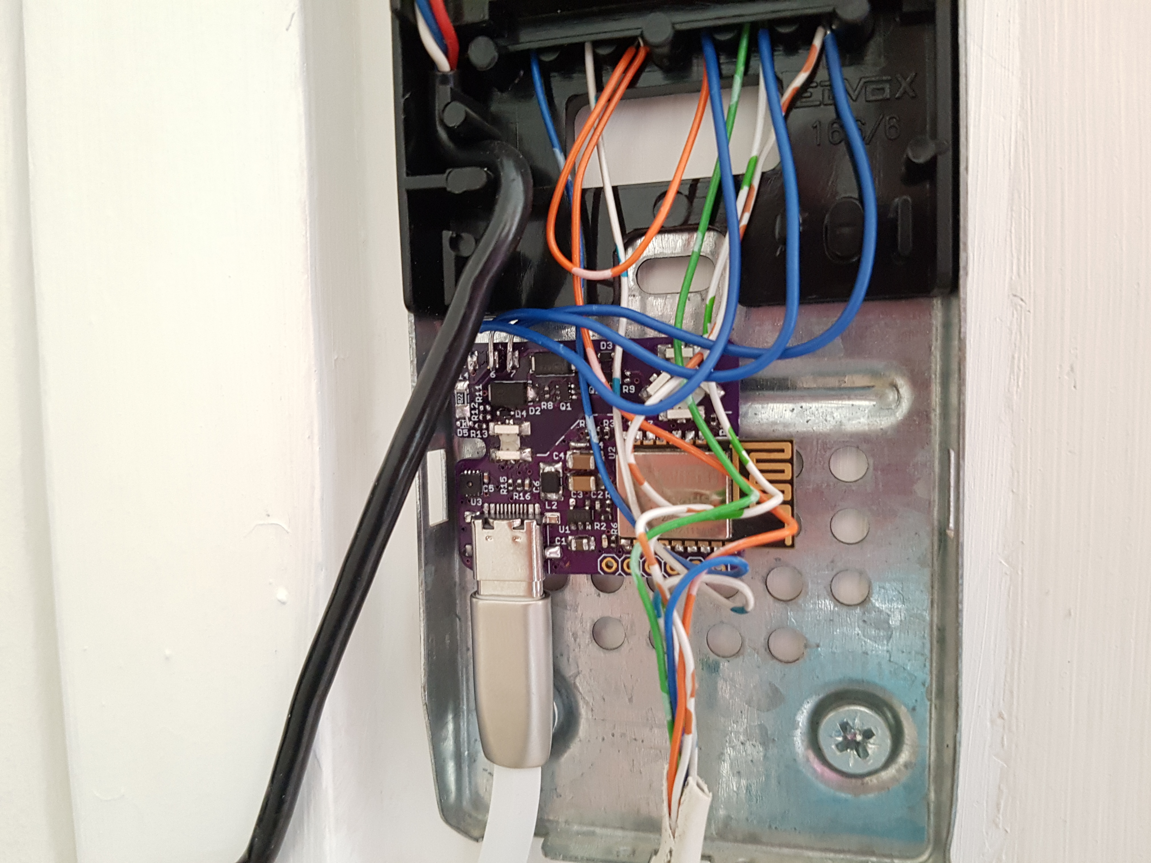
The Build
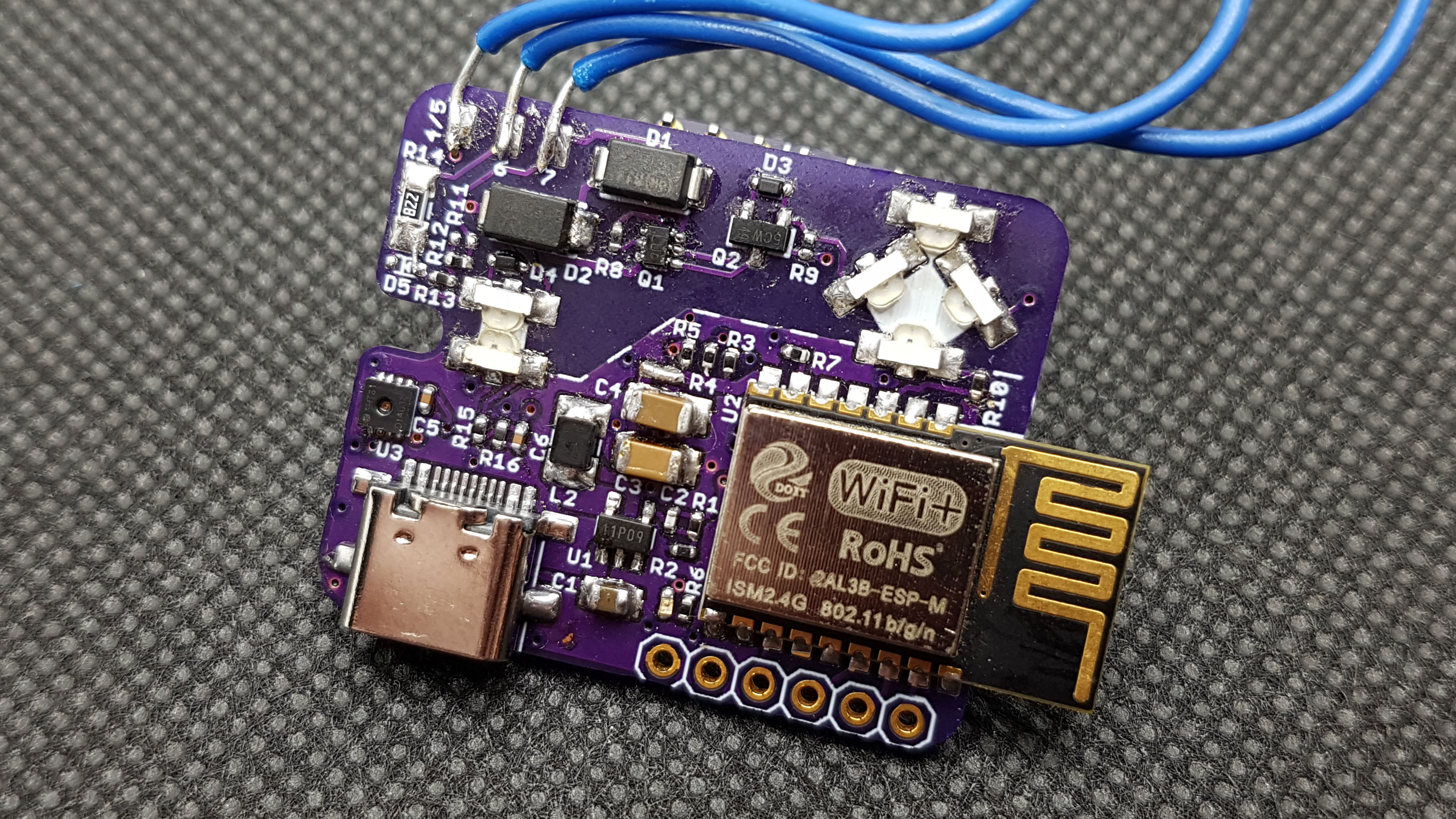
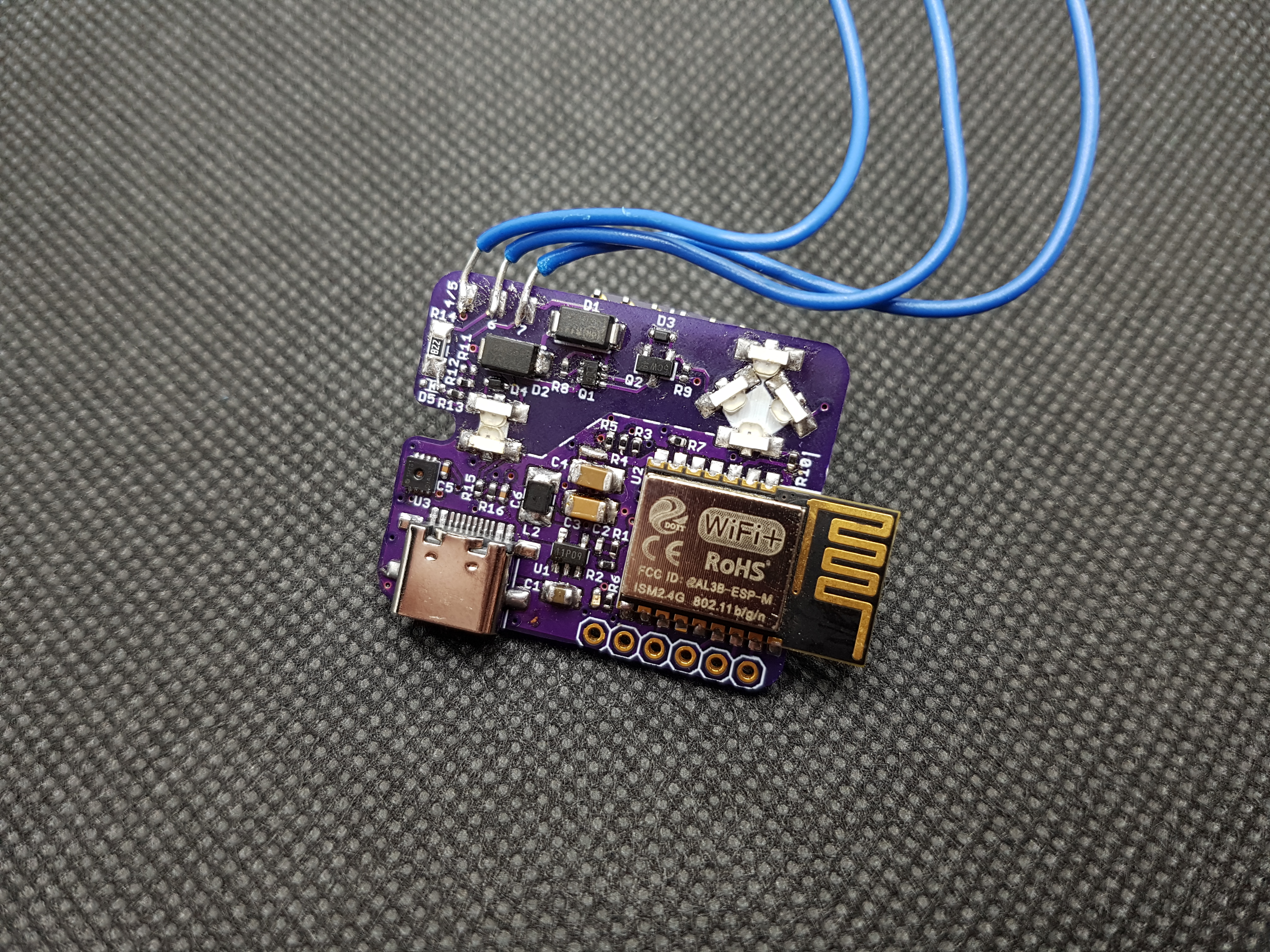
I decided to use an ESP-M2 WiFi module containing an ESP8285 (ESP8266 with embedded flash). Power is from a mains 5V USB charging adapter and goes through a 3V switching regulator. I was originally hoping to ‘steal’ some AC power from the intercom system through the lock solenoid, but I couldn’t quite condition the power draw of the ESP enough to stop the lock from making quiet buzzing sounds so I had to scrap that idea. It was also a pain having to run up and down the building every time I tried something (probably looked kinda weird too)!
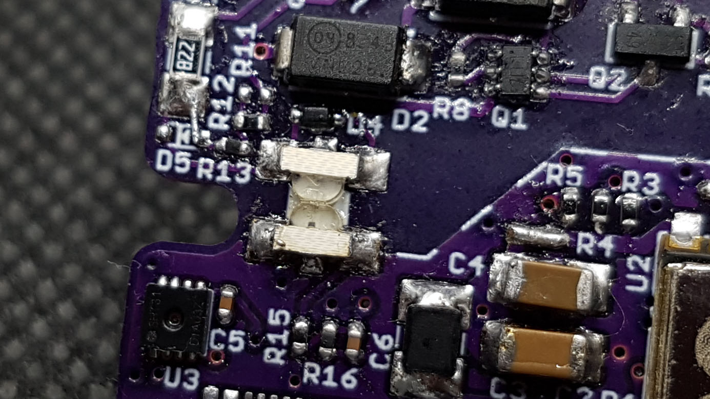
I didn’t want the intercom system electrically connected to the controller, so some opto-isolation was needed. Using the same opto-coupler and relay design from the prototype would have been too easy, so instead I made my own isolation with a bunch of LEDs! LEDs can also act as photodiodes and produce a small current when exposed to light, probably not quite as well as a purpose-built photodiode, but well enough for what I needed and much cheaper.
|
|
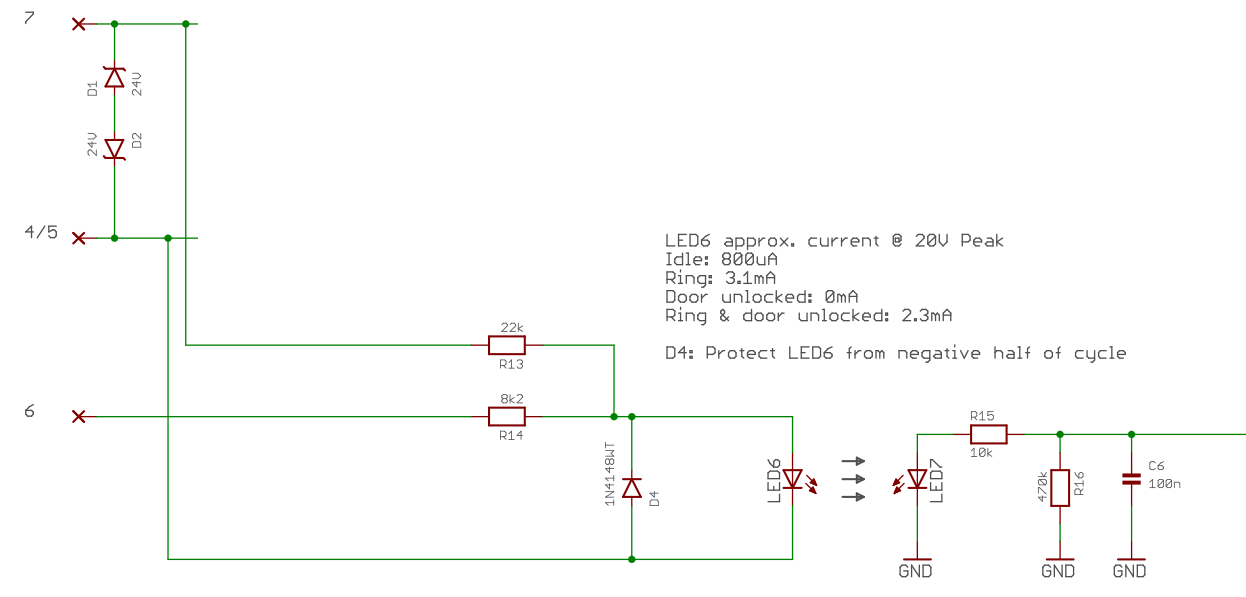
Buzz Detection
Detecting a buzz is done through 2 infrared LEDs (LED6, LED7; Kingbright KPA-3010F3C) creating an opto-coupler. LED6 is the emitter connected to the intercom ring wire and faces a sensing LED operating in photovoltaic mode – similar to a solar cell, it produces a current in the opposite direction to the arrow when light shines onto it. The sensing LED is connected to the ESP8285 ADC input through a low-pass filter. When the intercom buzzes the emitting LED shines onto the sensing LED which then produces a small voltage that the ESP can detect. The reason for the low-pass filter is that the intercom runs from a 50Hz AC power supply, so the sensing LED will also output a 50Hz waveform and the ESP would have the take an ADC sample roughly every 5ms to reliably detect something. However, the ESP didn’t seem to work too well when sampling the ADC this often as it is also used for various internal WiFi things, so instead the low-pass filter smooths out the waveform to allow sampling every 50ms.
|
|
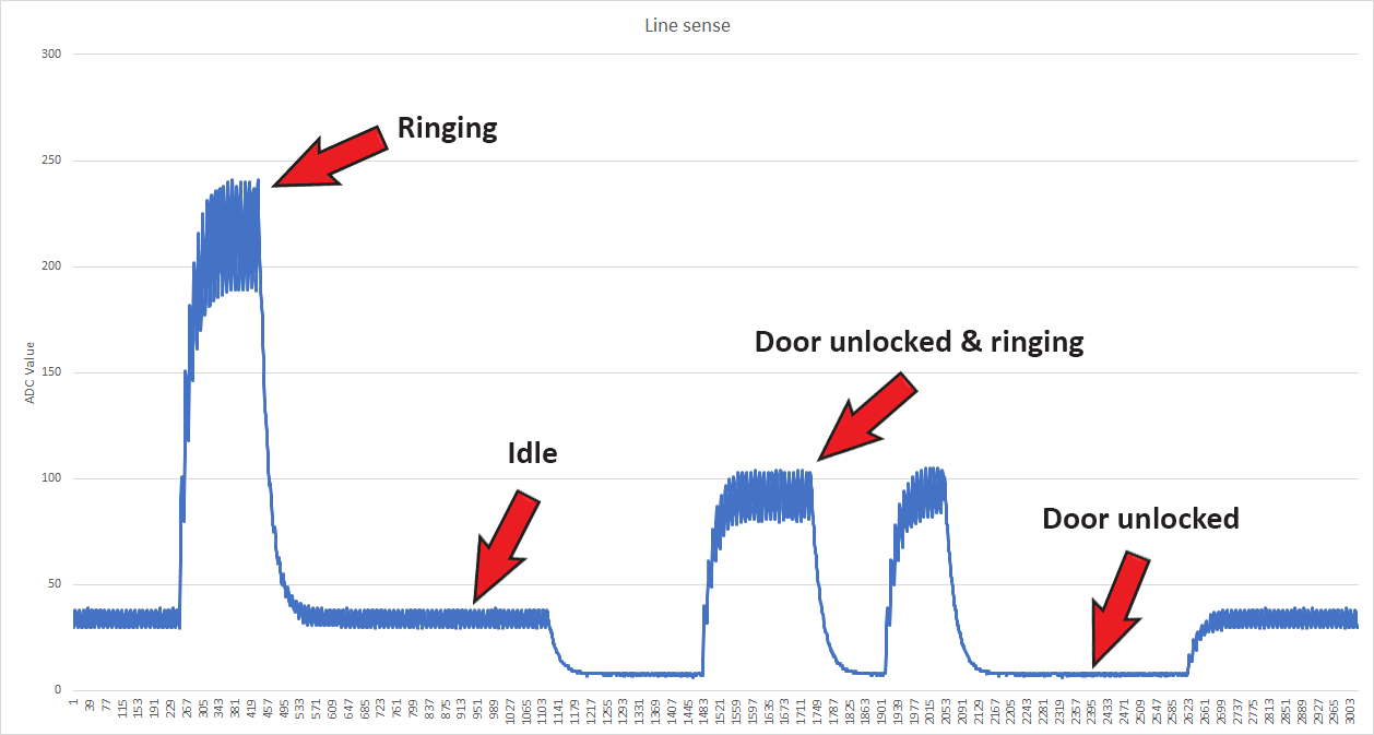
Since all of the intercoms in the building have their door switches wired in parallel it is possible to detect when someone else unlocks the lobby door from their intercom. With the right value resistors connecting the emitting LED to both the ring input and the door switch results with the LED shining at 4 distinct brightness levels, producing an equal number of distinct voltage levels at the ESP ADC input.
Unlocking the Door
The circuitry for controlling the door lock is made up of 4 infrared LEDs (same type as the ring detector), a dual MOSFET and a few other bits to make an opto-isolated solid-state AC relay. One emitting LED shines onto the three other sensing LEDs, producing a total of around 2V across them, just enough to turn on the MOSFETs. Two back-to-back 24V zener diodes protect the MOSFETs by clamping the high voltage inductive spikes mentioned earlier.
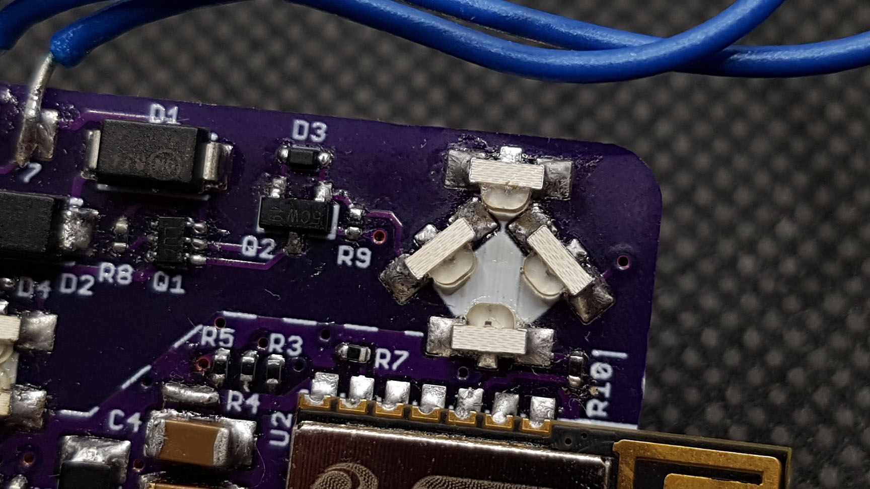
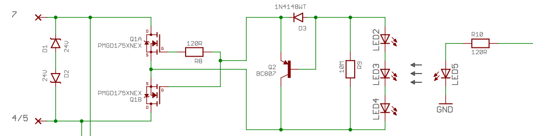
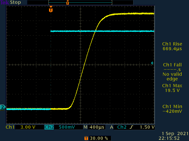
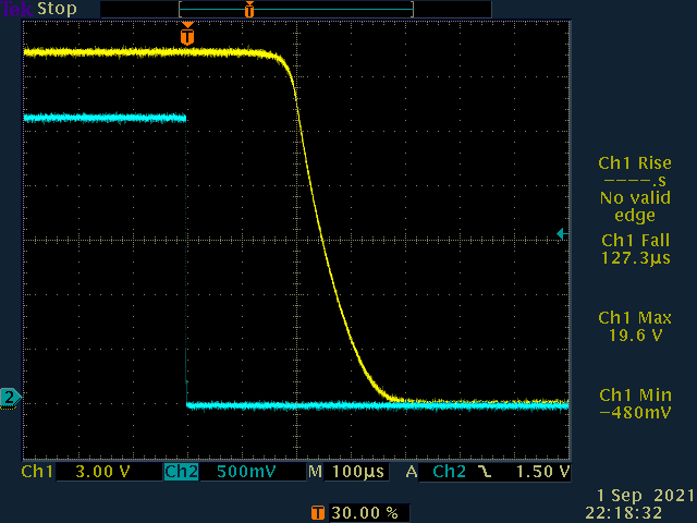
The current from the photodiode-LEDs is very small, so the MOSFET turn-on time is quite slow at around 1ms, though it’s still fast enough to turn on the solenoid and not burn the FETs. Turn-off time is much better with the help of the fast turn-off circuitry Q2, D3 and R9, at around 100us. R9 is a pretty large 10MΩ, a smaller value would help speed up the turn-off time, but if it’s too small then it will end up drawing too much current from the photodiode-LEDs and the FETs won’t be able to turn on.
I also think that using visible colour LEDs instead of infrared might have been better at producing higher currents and voltages.
Supply voltage: 20V DC
Yellow: Voltage across 32.5R test load (615mA @ 20V)
Blue: Output of ESP pin to emitter LED.
|
|
Internet of Things
A Node.js application runs on my server which hosts a Telegram bot and a WebSocket server. The ESP connects to the WebSocket server and transfers JSON messages whenever an event occurs. A message is then formatted and sent to a Telegram group chat informing members of these events.
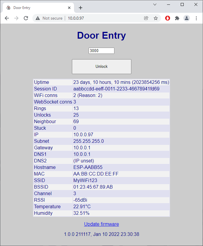
The JSON message sent for when a buzz is detected (it also includes a lot of extra information about its WiFi connection and things):
{
	"notify": "ring",
	"requestId": "",
	"millis": 1029721207,
	"session": "aabbccdd-eeff-0011-2233-46678941fd69",
	"disconnectreason": 0,
	"fw": {
		"version": "1.0.0 211117",
		"build": "Jan 10 2022 23:30:38"
	},
	"counts": {
		"wifi": 1,
		"ws": 1,
		"ring": 6,
		"unlock": 15,
		"neighbour": 40,
		"stuck": 0
	},
	"net": {
		"ip": "10.0.0.97",
		"subnet": "255.255.255.0",
		"gateway": "10.0.0.1",
		"dns1": "10.0.0.1",
		"dns2": "(IP unset)",
		"hostname": "ESP-AABB55"
	},
	"wifi": {
		"ssid": "MyWiFi123",
		"bssid": "01:23:45:67:89:AB",
		"channel": 3,
		"mac": "AA:BB:CC:DD:EE:FF",
		"rssi": -65
	},
	"env": {
		"t": 22.91447,
		"h": 32.31556
	}
}
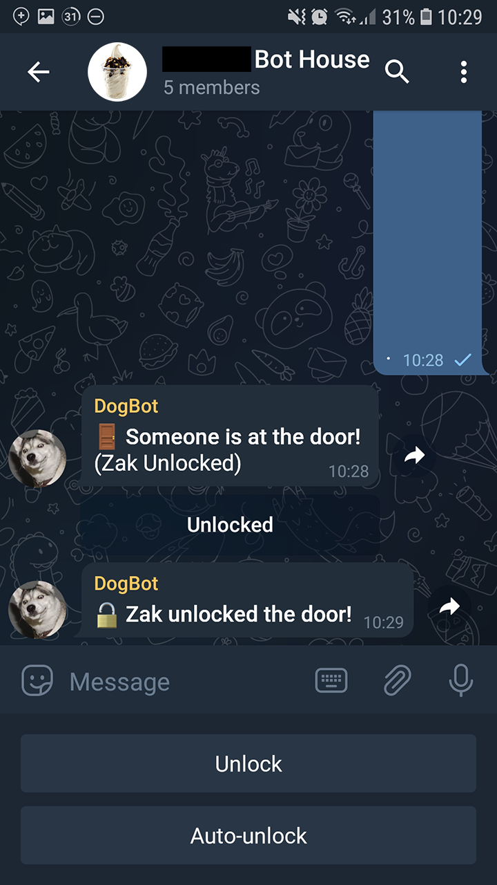
The door can be unlocked by the inline keyboard option or the by the /unlock command. The Node.js Telegram bot then picks this command up from the Telegram servers and relays a JSON message back to the controller, unlocking the door for 3 seconds:
{
	"action": "unlock",
	"duration": 3000
}
Other Things
There’s also an auto-unlock feature that will automatically unlock the door if the buzzer is pressed within 5 minutes, very handy for when I’m carrying up a load of shopping and I don’t want to fumble around with keys. The ESP hosts a local web server allowing control of the door lock without all of the Node.js and Telegram stuff and new firmware can be easily uploaded.
So why not have the Telegram bot run directly on the ESP? Unfortunately this would require every device to have its’ own bot account, and every device would be continuously polling for new messages from the Telegram servers. WebHooks can be used where Telegram instead initiates the connection for new messages, but this only supports 4 destination ports and so a maximum of 4 bots behind a home router/NAT.
Maybe I could add some voice recognition with a Raspberry Pi...
Schematics, firmware and everything can be found on my GitHub.
|
|
|
|
|

Comments
Skip to comment form